|
 |
| |
|
| |
 |
The coupling is used to transfer some power by connecting the drive shaft with the driven shaft.
The coupling is providing a wide range of choices in how to tighten the shaft.
It consists of corrosion-resistant aluminum alloy (Duralumin) with light and high stiffness,
so a revolution system with a small inertia can be driven.
It includes DRB, DRBS, DOH, DOHS, DJC, DJCS, DRJT, DRG, DRGL and etc.
other than DRN, DRJ and DRP.
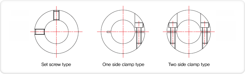
There are 3 types in how to tighten the shaft.
There are one set screw type and 2 clamp types in how to tighten the shaft. One of them can be optional.
Based on which type can be optimized,
different types or the diameter can be chosen depending on the shaft where the input and output are located. |
| |
 |
|
| |
 |
The following functional expression is required in having the coupling selected.
T(Torque) [N·m] = 9550 x P(Power) [kW] / Rev.N [min-1]
Selection Coefficient K by a fluctuation in the power.
In case there is a fluctuation in the power transmitted, according to its type, the coupling must be selected with a larger capacity of
transfer torque than the value by multiplied by Coefficient K.
No fluctuation to Less fluctuation: K=1.0~1.5
Intermediate fluctuation to More fluctuation K=2.0~2.3
Power conversion efficiency, transmission efficiency η
More power is required on the supplied side according to the efficiency when the power is recognized on the consumed side.
The selected power contributes to the choice of the coupling with a larger capacity of transfer torque than the power on the supplied
side. For example, in case of the conventional gear driving, larger power can be required due to the low efficiency in transmission.
Power Output(PO) [kW] = Coefficient K x Power Consumption (PS) [kW] / Efficiencyη : η< 1.0
The coupling can be generally chosen as torque value specified in the common transfer torque > the supplied power.
Note: when the servo motor generates much larger torque values to accelerate or decelerate during starting or stopping, the coupling can
be selected as a maximum transfer torque larger than the maximum startup torque multiplied by 1.5 on the motor.
The maximum transfer torque on the coupling < The maximum startup torque on the servo motorX1.5
The coupling can be selected as a larger value between the common transfer torque and the maximum transferring torque given. |
|
| |
 |
Besides the power chosen, the coupling includes the eccentricity, declination and the end play between 2 contacting shafts,
as well as the rev. No. being used. It is recommended that the rev. be applied lower than the maximum rev. as described
in the table showing the model No. of each page on the catalog. |
| |
 |
| Be sure that there is any coupling type which will not meet above requirements. |
| |
Torsional rigidity (the spring constant)
No. of frequency division for a feed screw can be calculated with the rigidity both on the coupling and the shaft.
Rigid kt coupled with the axis on a feed screw connected in series. |
1 / kt = 1 / ks + 1 / kc
|
ks : rigidity on the axis of a screw [N·m / rad]
kc : rigidity on the coupling [N·m / rad]
Ji : inertia on the input axis [N·m2]
Jo : inertia on the axial force [N·m2] |
|
| |
No. of frequency division (Fd) can be calculated from this kt and, Ji and Jo on
the input and output axes as the following steps.
Fd = 0.5 · (1 / π)· { 9.8 · kt ·(1/Ji +1/Jo) }-2 |
| |
Moment of inertia, a kind of inertia of revolving body, indicates the levels of difficulty when a moving torque (T) is
loaded on the revolving body.
Most of the Duri Couplings are designed with a light-massed compact body, so any value mentioned can be ignored in the process of
power transmission, but be sure that values must be checked as described in the table showing each type on the catalog when
calculating startup torques for multiple usage or the entire precise vibrations. |
|
| |
| |
|
|
|
|