|
 |
| |
|
| |
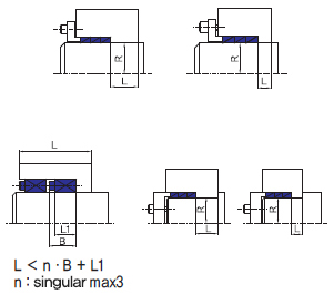
The Duri Locking Element provides users an opportunity to easily penetrate into spacers on the axis and hub, and a potential to transmit high torques.
Also, its axial direction can be easy to adjust. The product can give advantages such as improved designer's workability and working environment, as well as heightened strength on the key-free parts.
The Locking Element has common types compatible with other products, and can have extraordinary types in stock. For user's convenience, it has been customized in size and use. |
|
| |
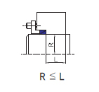
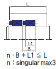
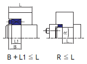
The Duri Locking Element is available for key-free power transmission on the axis and hub.
Absence of key grooves helps improve more strength on its parts and provide higher efficiency with the power.
The Locking Element can be used to tighten each part against the force on the axis(Fr), and also available for tightening the moving
axis and sprocket wheels, the moving axis and gears, and for transmitting the power against the moving torques (T).
In addition, it can be used as a rigid coupling by making a direct contact between axis.
General cautions in using the Locking Element
For individual caution, see the page of each model No.
- For transfer thrust values, it is illustrated how to clamp the Locking Element with a torque used as a standard bolt.
- Values for the maximum usable torque can be used less than the ones indicated depending on each model No.
If higher transmission or transfer torques are required, the bolts to be used can be tightened less than the maximum torque,
but increased pressure allows for selecting
- the materials used for the shaft and the hub. If the materials used exceed the yield point, make sure to check how the pressure
works in order to prevent the worst skids from giving any damage to the machine.
- Check to see if pressures on the yield point are described on the pages of the catalog.
- It is recommended that materials to be used be treated with heat for user's safety.
- If impact load is given to the product, the safety factor can be calculated at 3~5 times.
- If the shaft or the hub has no enough pressure, low transfer torque may result in skidding or the ring being fixed on the shaft,
so make sure to check how the pressure works. |
|
| |
 |
When starting the assembly work, oil can be lightly applied on the area where there is any friction between bolts and the rings connected
to the body. Lack of oil may lead to keeping transfer torques steady and as a result, the oil must be carefully checked. Make sure that the
oil will be EP addictive-free in it. Tighten the bolts diagonally with a wrench tool as the following steps Basically, the bolts can be equally
tightened to 25% of the standard torque first, then to 50% and finally to 100% respectively with each bolt locked once. |
|
| |
 |
| With all the bolts first taken out, new bolts must be inserted into the holes to start the work by uniformly tightening them on a diagonal line. |
|
| |
 |
Be careful not to have the Locking Element deformed and its bolts sagged after being assembled and disassembled.
The deformation or sagging will make the Lock become obsolete, so it must be replaced with new one. |
|
| |
 |
As the consumption power is selected, the supply power can be calculated based on the transmission efficiency.
With the Locking Element chosen, the materials must keep a yield point to which the pressure is allowable,
so that the Locking Element can hold a larger capacity of transfer torque than the power measured on the supplied side. |
| |
| Po [kW] = PS [kW] / η |
|
| |
 |
| T [N·m] = 9550 · K × Po [kW] / N [min-1] |
|
| |
 |
|
| |
 |
If there is a variable in the power transferred, the Locking Element will be selected, which has a larger capacity of common transfer
torque than the value multiplied by the next coefficient K, depending on how the power can change or whether there is an inertia or not. |
| |
No fluctuation to Less fluctuation
For light shocks, intermediate variable load or inertia
For strong shocks, vibrations or big inertia |
: K = 1.0~2.5
: K = 2.0~3.5
: K = 3.0~5.0 |
|
|
| |
 |
If combined loads (force of thrust + revolving torque) are given to the Locking Element, the following expression will be applied to select
the Locking Element, which has a larger capacity of transfer torque than this value after changing them into combined torque (Mh). |
| |
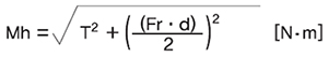 |
d : diamete |
|
|
| |
 |
If the Locking Element is used on the hollow axis, the value of inner diameter can be obtained from the following expression,
which is more than the diameter on the hollow axis. |
| |
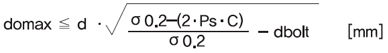 |
domax: the maximum inner diameter on the shaft.
d: the diameter /
Ps: Pressure on the side of the axis
σ0.2: the yield point by which the materials are selected
(see the table for yield strength)
C: Application constant
(see the table for application constants on the next page)
dbolt: the diameter of a bolt(if not used on the axis, dbolt = 0) |
|
| |
| Calculating the minimum diameter on the hub (Be sure that the outer diameter must be larger than the value above calculated.) |
| |
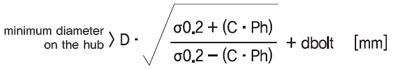 |
σ0.2 : the yield point by which the material is selected
Ph : Pressure on the hub
C : Application constant
dbolt : the nominal diameter of a bolt |
|
| Note) if there is any hole on the bolt of a hub, dbolt is applied. If not, dbolt is equal to 0. |
| |
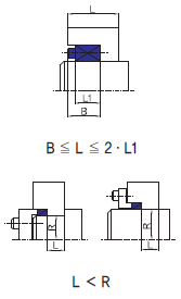
| C |
2-type shape can be illustrated based on the following condition. |
| If a single row is required |
If a multi row is required |
| C = 1.0 |
 |
 |
| C = 0.8 |
 |
 |
| C = 0.6 |
 |
|
|
|
| |
 |
| σ0.2 |
Material symbol |
Designation |
| Mpa [N/mm2] |
kgf/mm2 |
| 100 ~ 200 |
119 |
12 |
FC200 standard material |
Gray cast iron |
| 147 |
15 |
FC250 standard material |
Gray cast iron |
| 175 |
18 |
FC300 standard material |
Gray cast iron |
| SC360 standard material |
Carbon cast steel |
| SS330 standard material |
Rolled steel for general |
| 196 |
20 |
A2017-T4 |
Duralumin |
| 200 ~ 300 |
203 |
21 |
FC350 standard material |
Gray cast iron |
| 205 |
21 |
SC410 standard material |
Carbon cast steel |
| SUS304 standard material |
Stainless |
| 206 |
21 |
S10C standard material |
Carbon steel for machine structure use |
| SS400 standard material |
Rolled steel for general |
| 225 |
23 |
S15C standard material |
Carbon steel for machine structure use |
| SC450 standard material |
Carbon cast steel |
| 245 |
25 |
FCD400 standard material |
Nodular graphite cast iron |
| S20C standard material |
Carbon steel for machine structure use |
| SC480 standard material |
Carbon cast steel |
| SS490 standard material |
Nodular graphite cast iron |
| 265 |
27 |
S25C standard material |
Carbon steel for machine structure use |
| 274 |
28 |
S30C standard material |
Carbon steel for machine structure use |
| 280 |
29 |
FCD450 standard material |
Nodular graphite cast iron |
| 290 |
30 |
A2024-T4 |
Super duralumin |
| 294 |
30 |
S35C standard material |
Carbon steel for machine structure use |
| 300 ~ 400 |
320 |
33 |
FCD500 standard material |
Nodular graphite cast iron |
| 325 |
33 |
S40C standard material |
Carbon steel for machine structure use |
| 343 |
35 |
S45C standard material |
Carbon steel for machine structure use |
| 365 |
37 |
S50C standard material |
Carbon steel for machine structure use |
| 370 |
38 |
FCD600 standard material |
Nodular graphite cast iron |
| S55C standard material |
Carbon steel for machine structure use |
| 400 ~ |
420 |
43 |
FCD700 standard material |
Nodular graphite cast iron |
|
| |
The materials can be selected based on the point by which each pressure on the side is bearable by checking the pressure given to the shaft and hub by transmission power and torques.
This value can be applied to calculate the minimum diameter on the hub and the maximum diameter on the axis hole.
SS400, S15C~S55C are written in bold type. Standard materials listed in the table show that the materials used are not treated with heat.
Be careful not to have some metals with low yield strength even in the process of heat or surface treatment.
The products made of cast iron have no yield strength with them, so 70% of their tensile strength can be replaced with what a diameter on the hub has been calculated. Duralumin extension (-T4), treated with heat, has hardened for 4 days, stored at room temperature. |
|
| |
 |
Strength class
size x pitch |
Max tightening Force |
Max tightening Torque |
| 8.8 |
10.9 |
12.9 |
8.8 |
10.9 |
12.9 |
| N |
N |
N |
N·m |
N·m |
N·m |
| M2.5 × 0.45 |
1,500 |
2,140 |
2,570 |
0.7 |
1.0 |
1.2 |
| M3 × 0.5 |
2,230 |
3,180 |
3,820 |
1.3 |
1.8 |
2.2 |
| M4 × 0.7 |
3,900 |
5,450 |
6.550 |
2.9 |
4.1 |
4.9 |
| M5 × 0.8 |
6,350 |
8,950 |
10,700 |
6.0 |
8.5 |
10 |
| M6 ×1 |
9,000 |
12,600 |
15,100 |
10 |
14 |
17 |
| M8 × 1.25 |
16,500 |
23,200 |
27,900 |
25 |
35 |
41 |
| M10 × 1.5 |
26,200 |
36,900 |
44,300 |
49 |
69 |
83 |
| M12 × 1.75 |
38,300 |
54,000 |
64,500 |
86 |
120 |
145 |
| M14 × 2 |
52,500 |
74,000 |
88,500 |
135 |
190 |
230 |
| M16 × 2 |
73,000 |
102,000 |
123,000 |
210 |
295 |
355 |
| M18 × 2.5 |
88,000 |
124,000 |
148,000 |
290 |
405 |
485 |
| M20 × 2.5 |
114,000 |
160,000 |
192,000 |
410 |
580 |
690 |
|
| |
| |
|
|
|
|